PCB Assembly
Tools Required
- Soldering iron
- Pliers
- Wire cutters
- Desoldering pump (solder sucker)
- solder
- Breadboard
Preparatory Steps
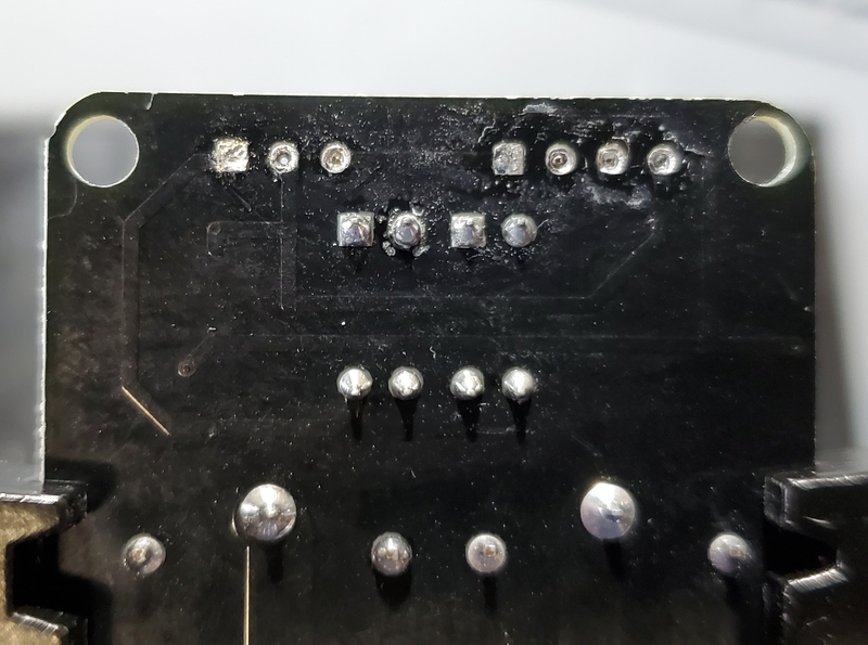
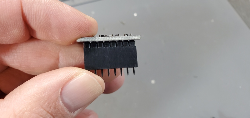
Reverse the direction of pins on 2 relay module
1. Pull plastic base up and off using a pair of pliers.
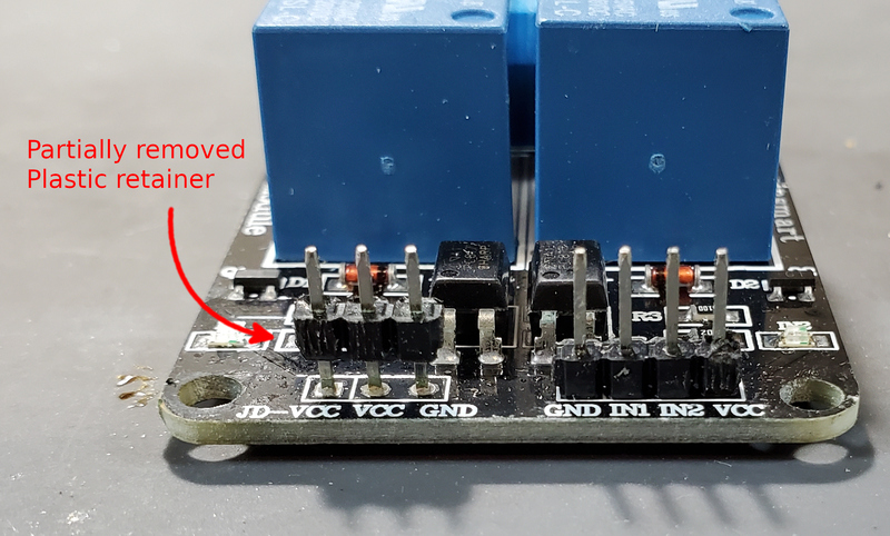
- Tip - If it is difficult to remove the plastic base, cut the base so it only is connect to a single pin. Then pull it off.
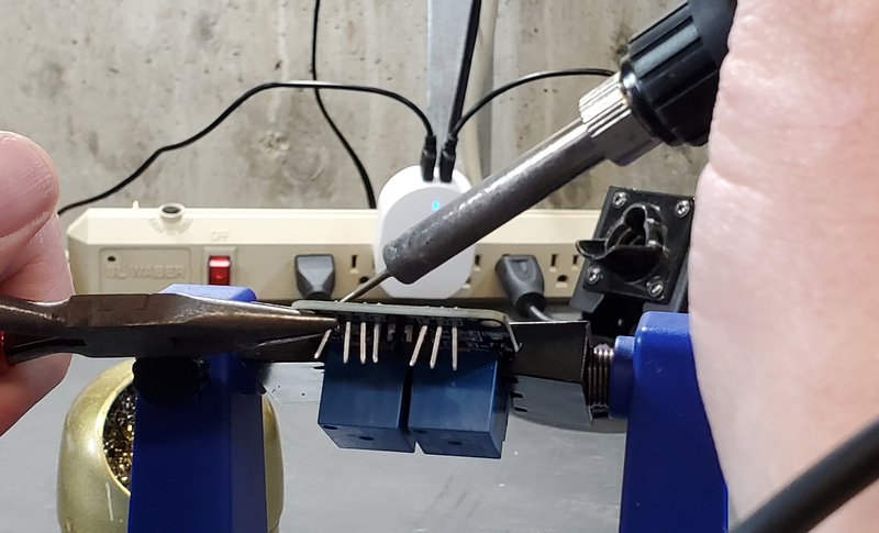
2. Remove pins by grasping the longer end of the pins with a pair of plier and gently pulling away from the board while simultaneously heating the solder with the iron to release the pin.
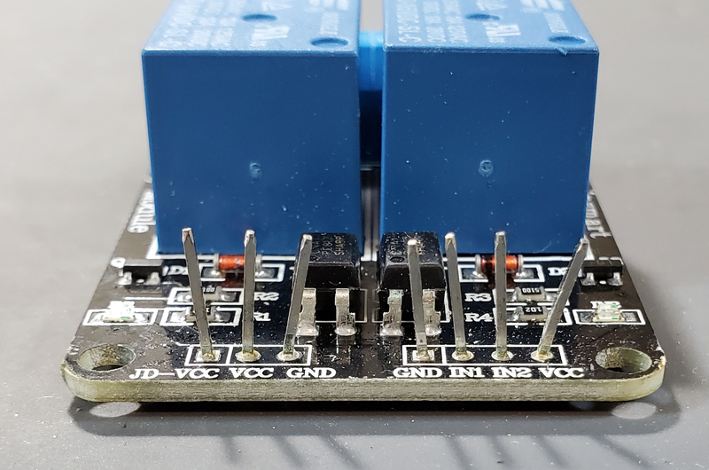
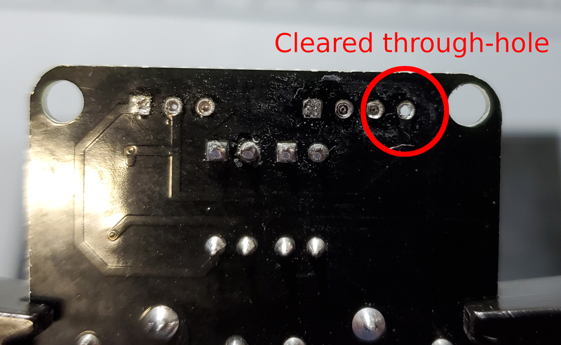
When you have completed this step, the through-holes on the board will likely still be filled with remnant solder.
3. Next, remove solder from the through-holes by placing the aperture of the solder sucker directly over a through hole, while simultaneously heating the solder in the through hole with the soldering iron. When the solder liquefies, fire the solder sucker to remove the solder from the hole. You may need to repeat this step multiple times per through-hole to completely clear the hole of solder. Be careful not to leave the soldering iron on the through-hole too long and cause the pad to separate form the PCB.
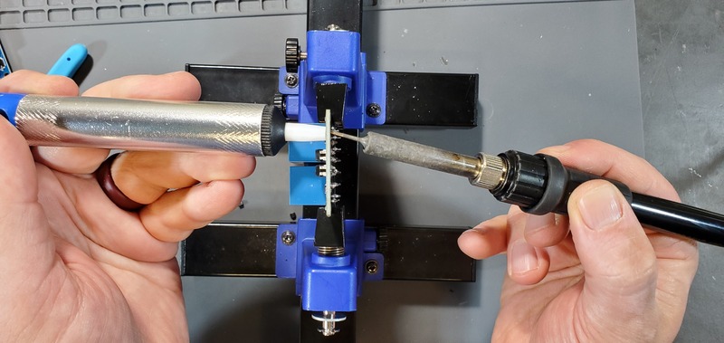
You may need to remove soldier from both sides.
You can check by attempting to push the clean end of one of the removed pins through the joint. If you can push the pin through easily, it has been cleared. If it fits through, but tightly, you can spin the pin (which should be square in cross-section) in the hole to clear away the last few bits of solder.
4. Finally, solder on new pins in the reverse orientation.
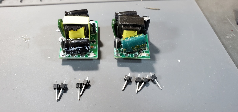
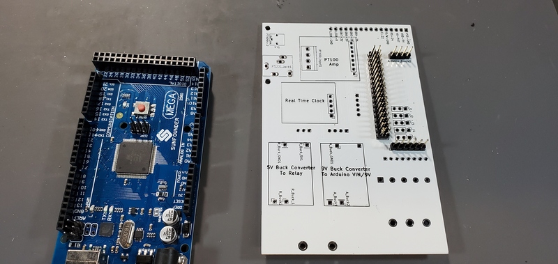
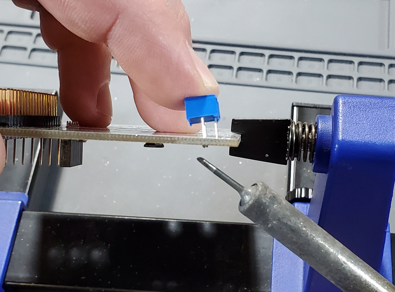
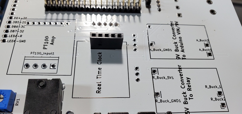
Prepare 5V and 9V buck converters
-
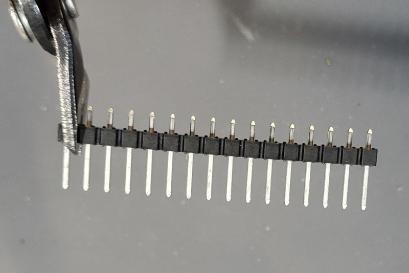
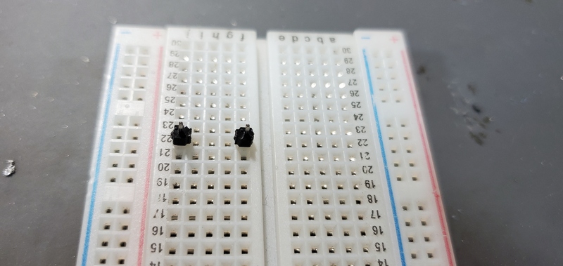
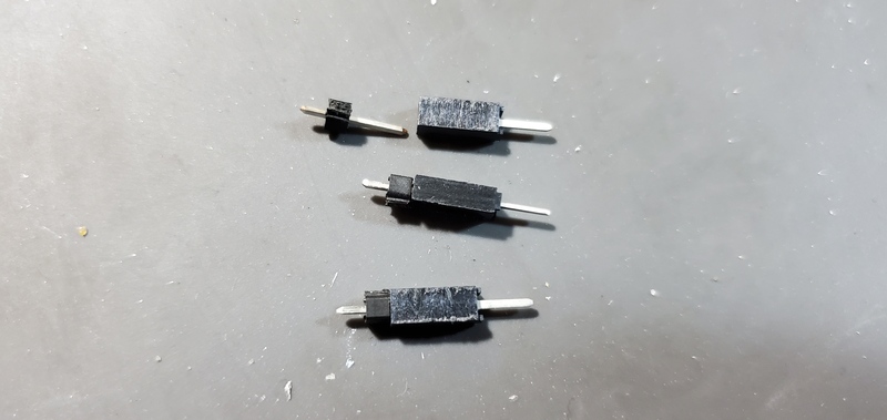
The bill of materials includes two 16-pin male headers. We will use one of these to supply single pin male headers. Use pliers or wire cutters to break off eight single male header pins.
-
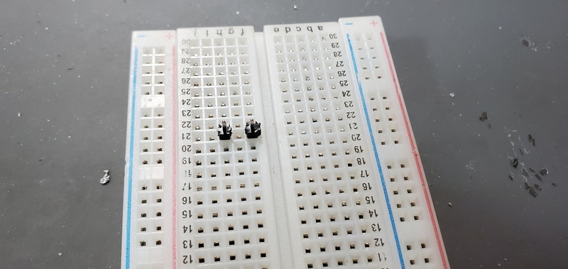
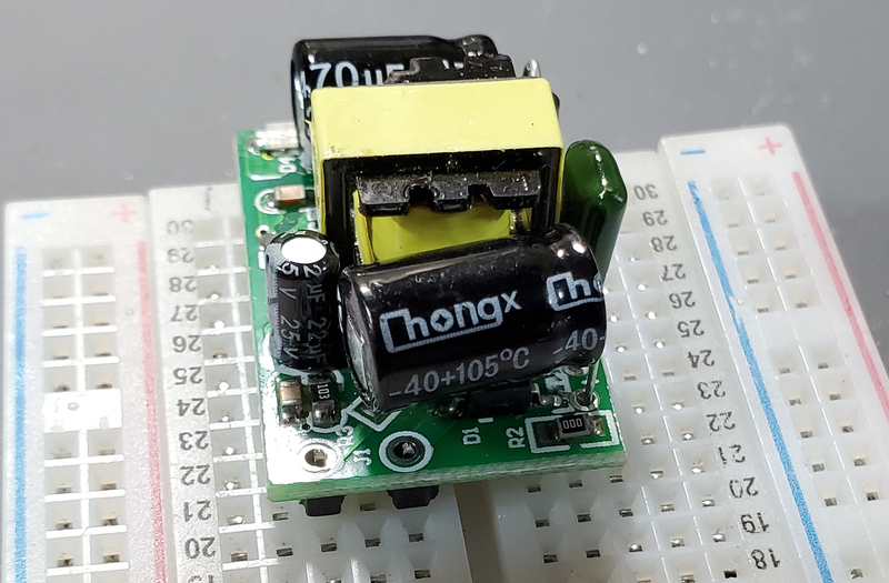
Put two single male header pins on a breadboard two positions apart, somewhere towards the middle of the board, then put buck converter on top
-
Solder those two pins in place
-
Place two pins four positions apart on the breadboard 9 rows away from the end of the breadboard (this should allow just enough room for the two pins previously soldered to hang over the edge.).
-
Place buck converter on top of these pins. These pins are very close to a large capacitor that may have to be bent upwards away from the pins in order to safely solder.
-
Repeat with second buck converter.
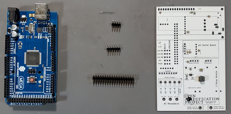
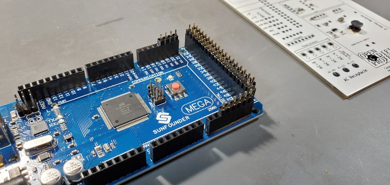
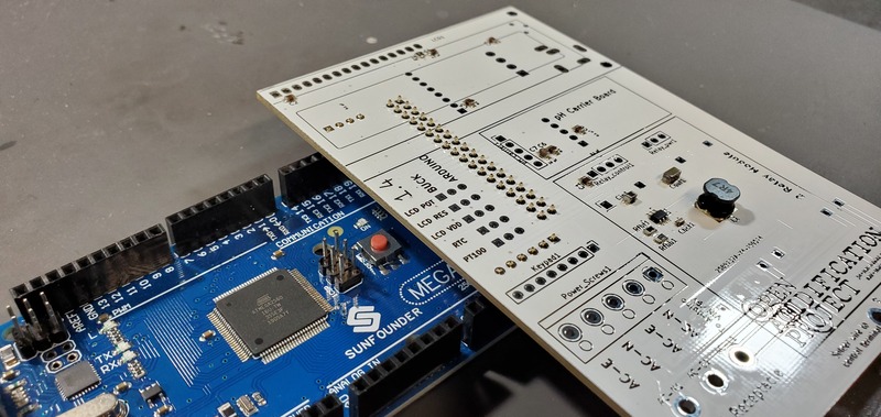
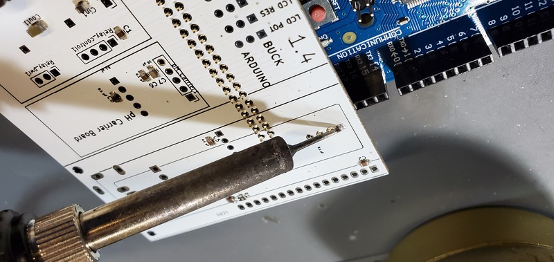
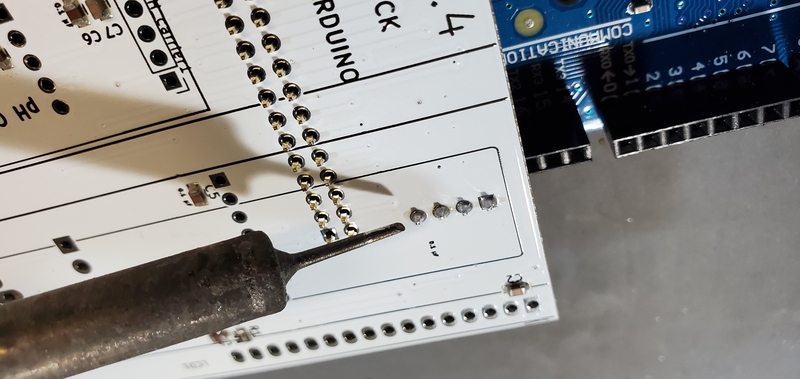
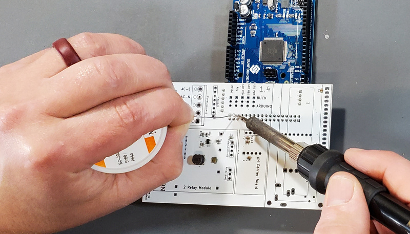
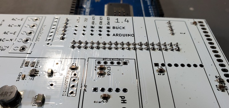
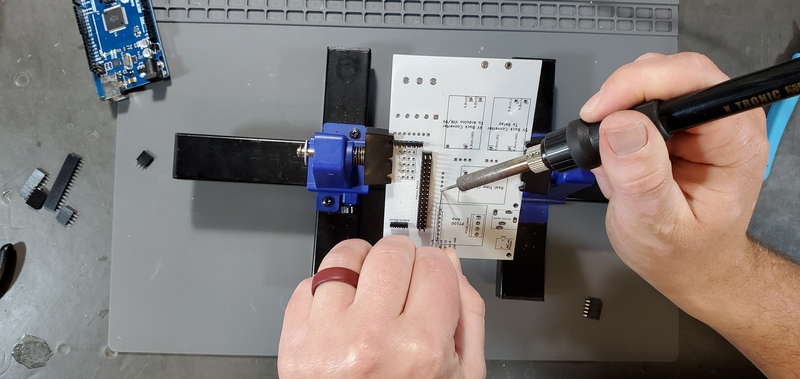
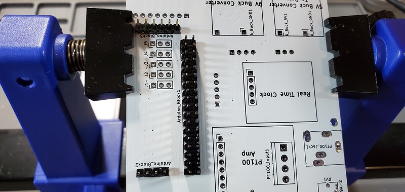
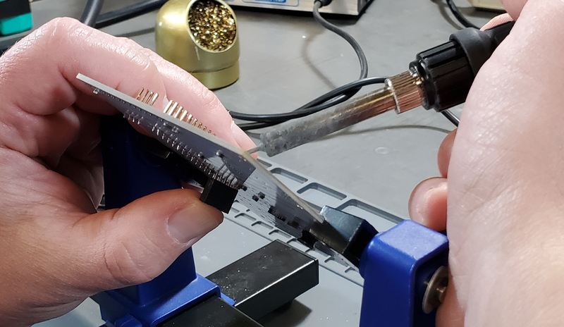
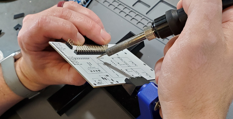
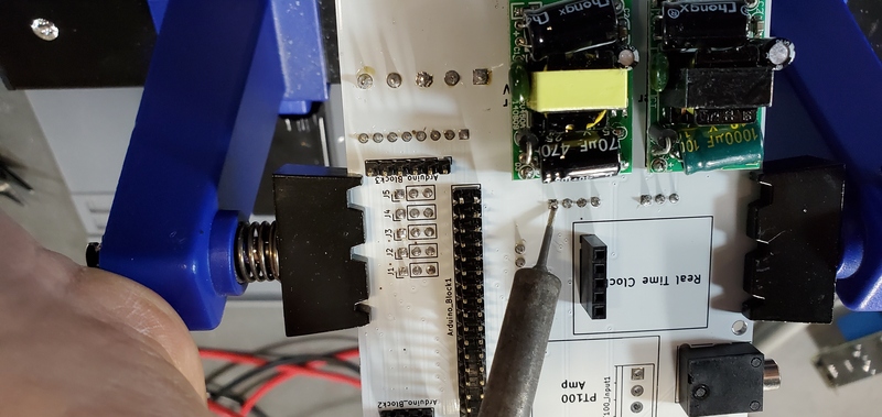
Solder Arduino Header Pins to PCB
- Arduino Mega
- 1x 2.54 mm 4 header pins
- 1x 2.54 mm 6 header pins
- 1x 2.54 mm 2x18 header pins
- Custom PCB
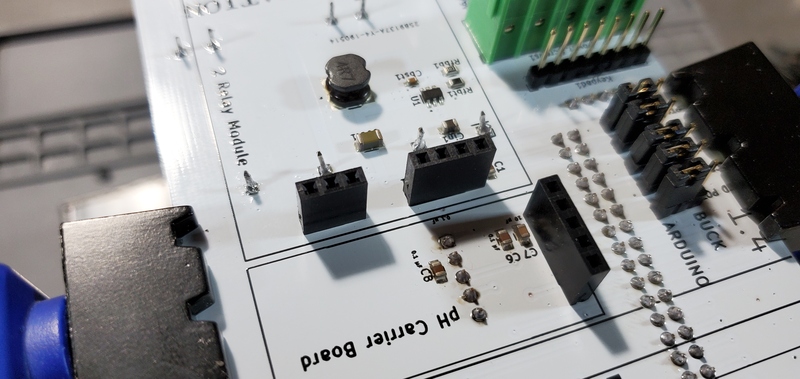
Attaching pH Carrier Board Female Header
- 5 position female header for the pH carrier board
-
Custom pcb
There are many methods one could use to attach this header. Here we demonstrate how we have done it.
-
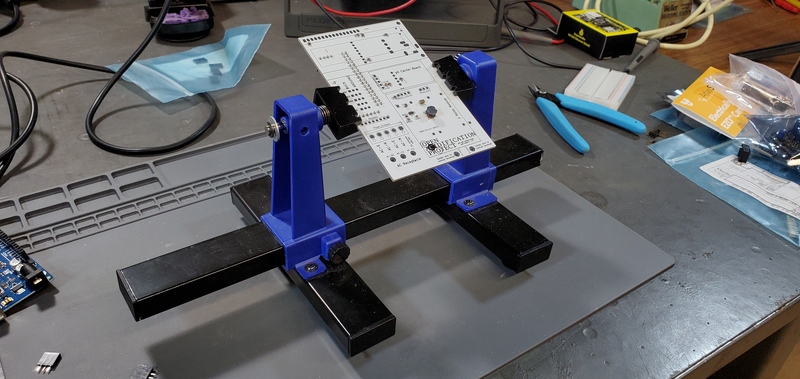
Fill first through hole with solder (We use a PCB holder for this process)
-
Position the five pins of the header along the five through holes in the box labeled “pH carrier1”. Pay attention to the header is on the opposite face of the PCB from the Arduino header pins. Once placed press gently against the pin placed in the filled through hole.
-
While pressing header pin against filled through hole, heat the other side of the through hole with your soldering iron. Your pin should fall through the hole and become attached to the board.
-
Now that the first pin is set and the header provisionally attached, you can reheat the pin to melt the solder and reposition the header if alignment needs to be adjusted.
- Finally, solder the remaining pins on the header. This will be the basic process for attaching all other headers to the board, so we will not reiterate the whole process each time.

Attach Header for the Keypad
Using the same method you used to attach the pH carrier board female header, solder on the 8-pin male header for the keypad.
Make sure that these pins are placed on the opposite face of the PCB as the Arduino header pins.
Potentiometer
Solder on the potentiometer.
Make sure this component is soldered onto the same face of the PCB as the Arduino header pins.
3.5 mm Jack
Solder the 3.5mm jack onto the same face of the PCB as the Arduino header pins.
This component has larger solder pins and will require more solder.
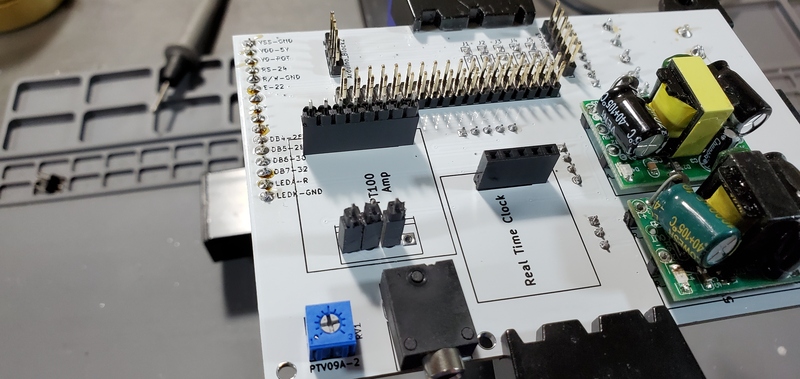
Realtime Clock Female Headers
Solder on a 5-position female header on the Real Time Clock location on the PCB on the same face as the Arduino header pins.
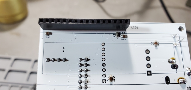
LCD Header
Solder on a 16-position female header onto the LCD1 position on the opposite face of the PCB from the Arduino header pins.
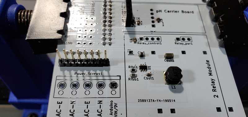
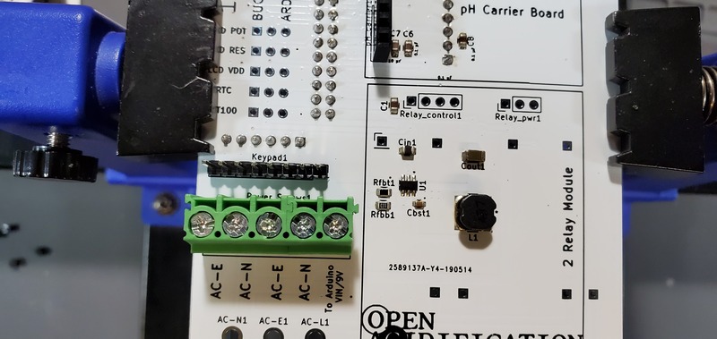
Power Screw Terminals
Solder on the large screw terminals onto the PCB onto the face opposite the Arduino header pins in the location labeled “Power_Screws1”.
The openings on the side of the terminals (where the wires will be fed) should be facing toward the “AC Receptacle” location on the PCB.
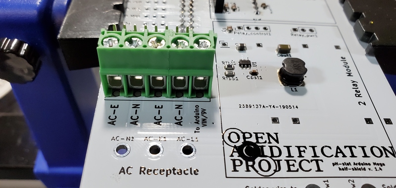
Solder on the large screw terminals onto the PCB onto the face opposite the Arduino header pins in the location labeled “Power_Screws1”. The openings on the side of the terminals (where the wires will be fed) should be facing toward the “AC Receptacle” location on the PCB.
Jumper Pins
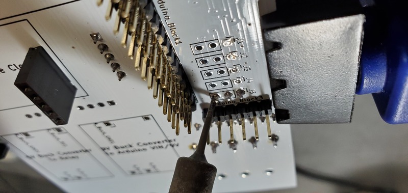
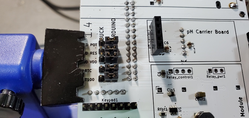
Solder 5 3-pin male headers onto the positions labeled “LCD POT”, “LCD RES”, “LCD VDD”, “RTC”, and “PT100” inside the Arduino header pins, but on the opposite face of the PCB rom the header pins.
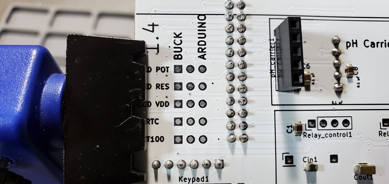
Since these pins will be on the opposite face as the Arduino header pins, and therefore you will be soldering on the side with the long Arduino header terminals, you will need to use a rather steep angle with your soldering iron.
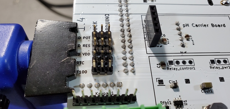
Once they are soldered on, place jumpers between the center pin and the “Arduino” pin on each header.
AC Power Receptacle
Next, solder the AC receptacle onto the opposite face of the PCB from the Arduino header pins.
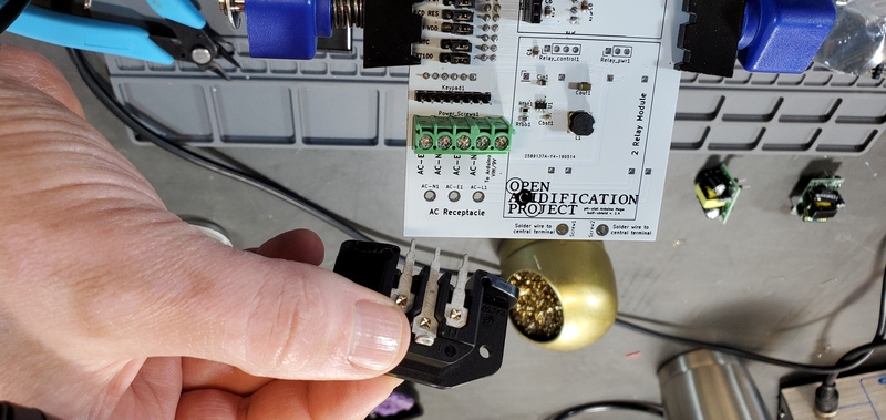
I find the easiest way to do this is to hold the AC receptacle from underneath the PCB into it’s through holes and then place a small chunk of solder near on of the terminals.
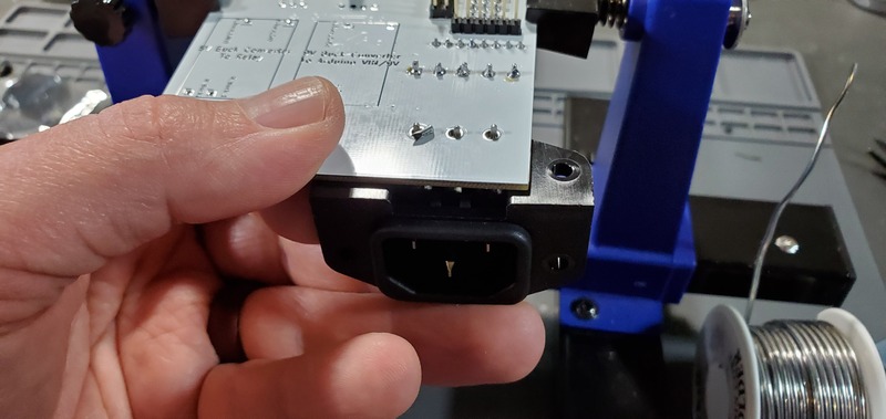
Then I can solder on that pin with that solder chunk.
Then I can easily solder the remaining pins.
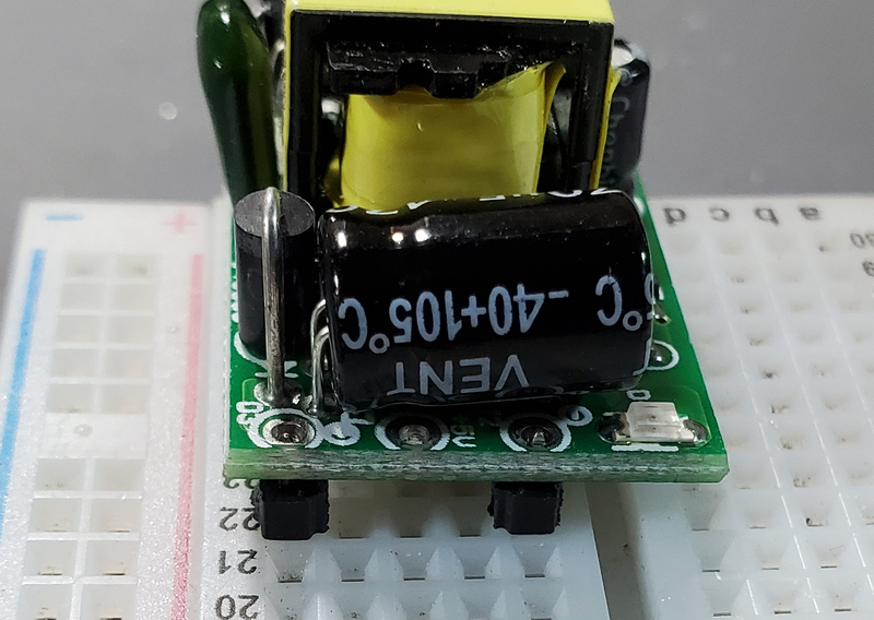
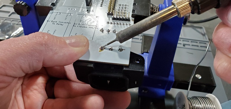
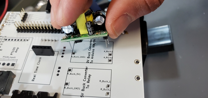
Attach Buck Converters
Now place the buck converters onto the PCB on the same face as the Arduino header pins.
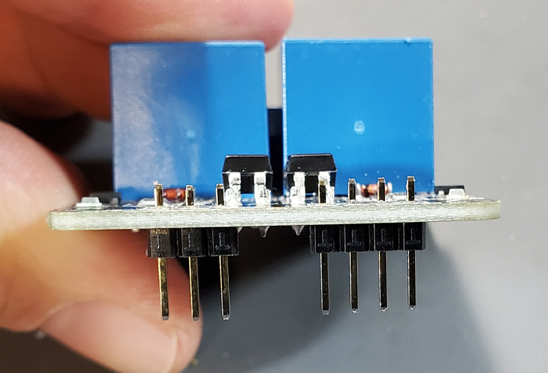
The through holes for these converters are slightly closer together on the PCB than on the converters.
This is intentional so that you can place them and have tension keep them in place while you test the units before soldering them on.
Make sure that you place the correct buck converter in the correct place on the PCB.
The positions are marked on the PCB.
The 5V buck converter should have a 1000 μF capacitor on the output end, the 9V should have a 470 μF capacitor in the same position.
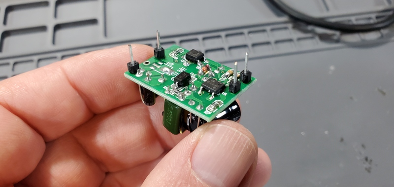
Testing buck converters before soldering
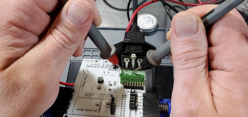
Before soldering the buck converters to the PCB you should test the outputs to make sure 1) that you placed the buck converters in the correct positions and 2) that the converters are not defective. To do this we need to plug the board into an outlet, which must be done very carefully to prevent giving yourself a very dangerous shock. To do this safely, first secure the PCB so that it remains in place while plugged in. I suggest using a PCB holder for this. Then, plug the power cable into the PCB. Only then plug the power cable into a wall outlet. Once the PCB is plugged into the wall, DO NOT TOUCH IT except with the multimeter. If you need to reposition the board, unplug it from the wall before doing so.
Once you have the PCB secured and plugged in, use a multimeter to check the voltage output on both the 5V and the 9V buck converters.
This is most easily done on the pins protruding through the PCB on the opposite face of the buck converters.
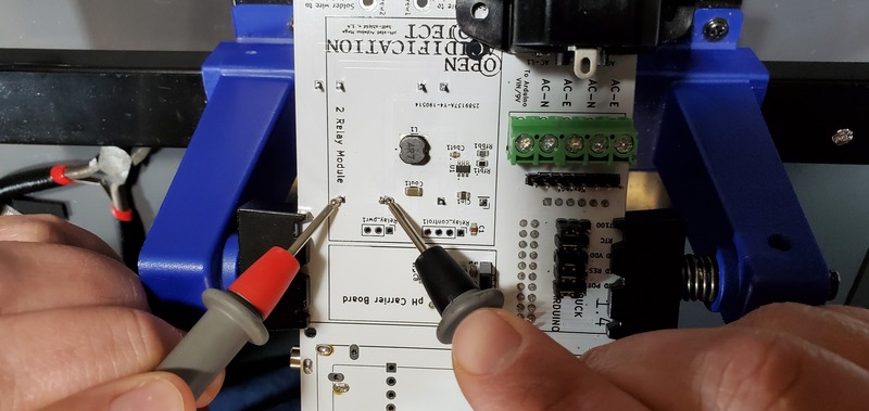
It is also useful to check the 7V power output from the screw terminal block for the arduino.
You can do this by checking voltage between the screws labeled “To Arduino VIN/9V” and “AC-E”.
Soldering buck converters in place
Once you have check the voltage outputs of the buck converters, confirming correct placement and that they are in working order, you can solder down those two devices. Before you do this, however, UNPLUG THE PCB BEFORE MOVING OR ATTEMPTING TO SOLDER the buck converters. After you have solders all 4 pins on each buck converter, you can trim the pins on the opposite face from the buck converter with a wire cutter.
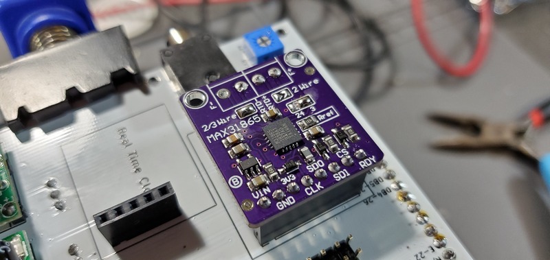
PT100 Temperature Probe Breakout Board
Next we will attach the headers and configure the MAX31865 PT100 temperature probe break out board.
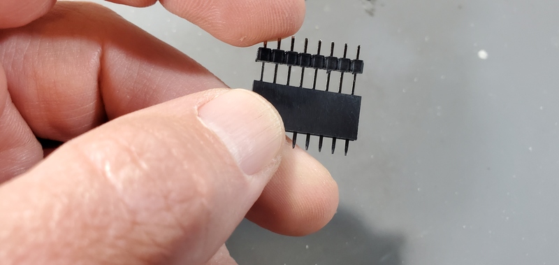
You will need the 8-pin male header that came with the breakout board, a 8-pin female header, three 1-pin female headers, and clip off 3 1-pin headers from the spare 16-pin header as you did with the buck converters.
You will not need the two screw terminals that come with the pt100 breakout board.
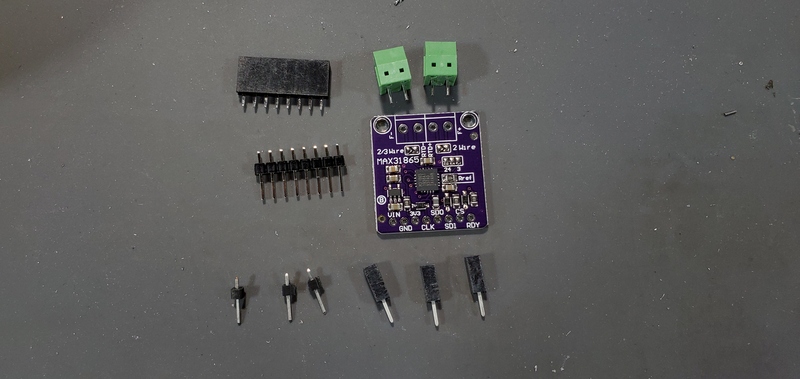
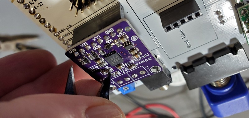
To attach the board to the PCB, first place the 8-pin male header into the 8-pin female header.
Next, place the 1-pin male headers into the 1-pin female headers.
Place each of these mated male/female headers into the PCB on the position marked “PT100 Amp”, with the pins for the female headers placed into the PCB.
There are 3 single pin headers, but 4 positions to place them.
Place them into the three positions closest to the edge of the the PCB.
Then, place the pt100 breakout board on the male side of the header pins and solder into place.
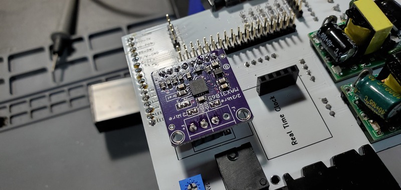
Following soldering the pt100 breakout board, you can also solder the female header pins on the PCB.
Configuration of the PT100 breakout board
On the PT100 breakout board solder together the pads that are labeled “2/3Wire”
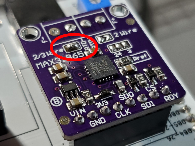
Next, use a sharp instrument (I use the pointed tip of my wire cutters) to cut the jumper between the “2” and “4” pad on the “2 4 3” jumper.
Finally, on that same jumper set, solder together the “4” and “3” pads.
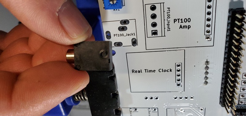
Attach Real Time Clock Breakout Board
This component ships with a 5x1 set of header pins.
We need the pins facing down (away from the battery), so they will be soldered from the front of the board.
A good way to do this is to put the male pins into a breadboard, then place the breakout board on top of the pins (perhaps with some padding to have the breakout board at a right angle from the pins).
You can then solder the header pins and remove the breakout board from the breadboard.
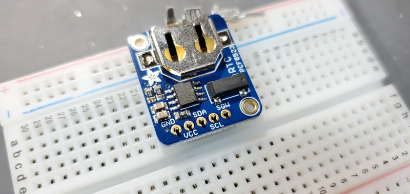
Then place on the female header on the PCB. Finally, put a CR1220 coin battery into the breakout board.
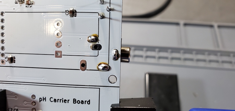
Attach the Atlas Scientific EZO pH Breakout Board
Remove the electrically isolated EZO carrier board from the packaging, and attach the header as you did with the RTC breakout board.
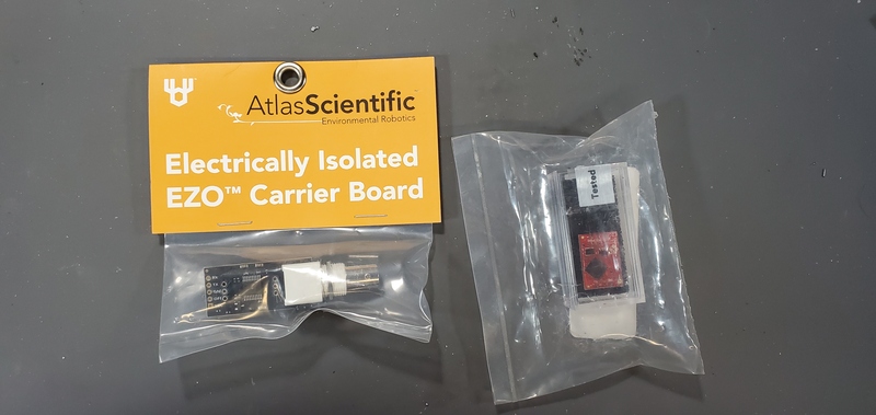
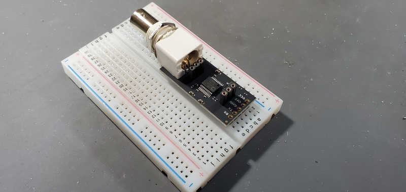
Next, place the red EZO pH stamp on the carrier board so that the “PH EZO” lettering is closest to the large white plastic part of the carrier board and the BNC plug.
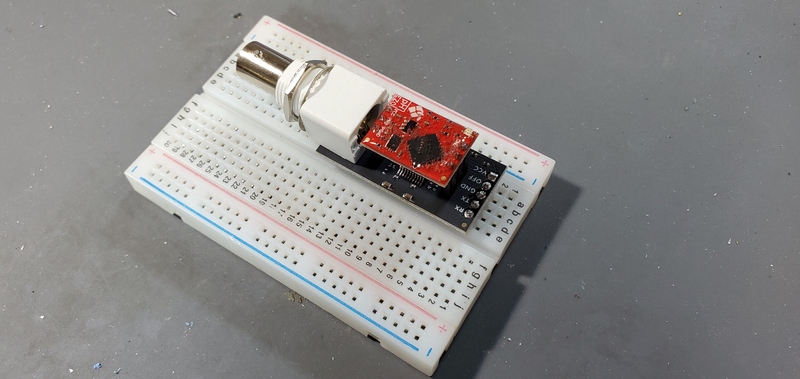
Finally, place the entire assembly on the “pH carrier board” position on the PCB by inserting the male header on the carrier board into the female header on the PCB.
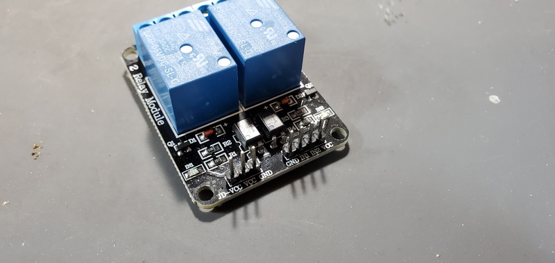
2-relay Module Attachment
First, solder the 3-pin and 4-pin female headers onto the PCB on the side that is opposite the Arduino header pins.
To make this easier, you may temporarily remove the real time clock, PT100 and EZO pH breakout boards from the PCB by unplugging them from the PCB and setting them aside.
Next, place the 2-relay module onto the PCB by plugging it into the female headers.
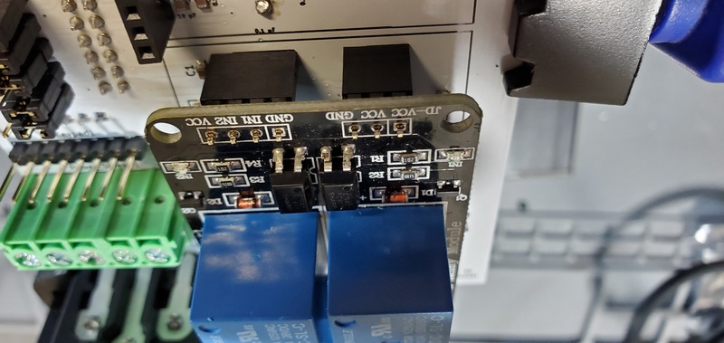
Attaching high voltage wires to relay
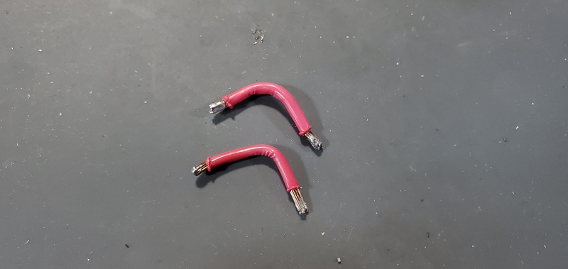
Cut two pieces of stranded 14 gauge (AWG) wire to a length of approximately 3.5 cm.
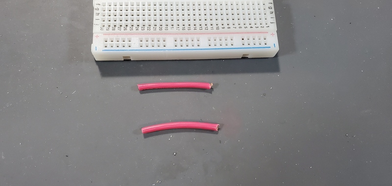
Strip the insulation of the last 5mm of each end.
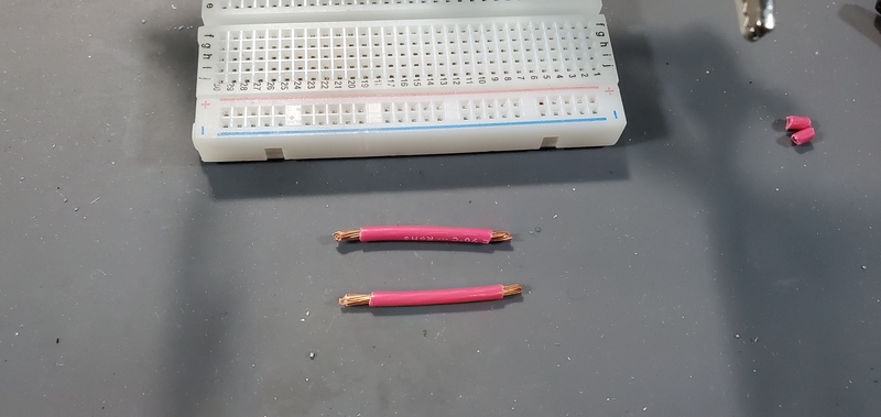
Tin the ends of the wire where it is not covered by insulation.
This involves heating the bare wire with the soldering iron, and melting solder into the wire, allowing the strands to “wick” up the solder.
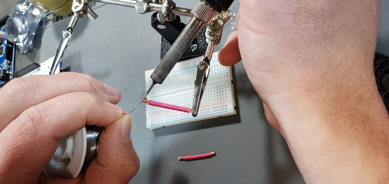
Next, bend the wires approximately in the middle.
Next, place one end of the wire in the middle terminal of each of the two 3-position terminal screw blocks on the relay module and place the other sides in the hole in the PCB labeled “Screw1” and “Screw2”.
Tighten the screws to secure the wires into place.
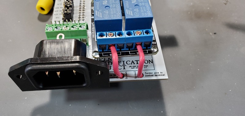
Finally, solder the ends of the wires in the PCB to the holes.
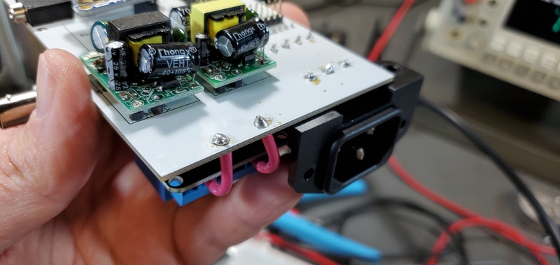
Now, you are finished assembling the custom PCB.