Device Assembly
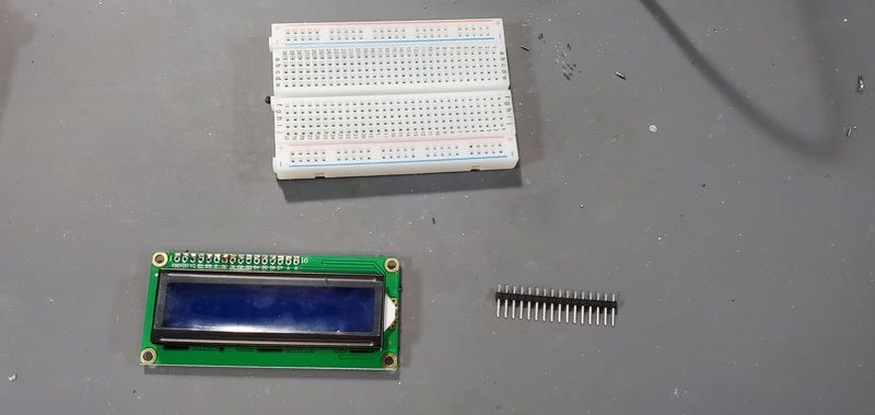
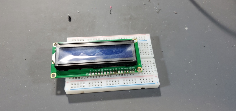
Solder header pins to LCD module
Solder the 16-pin male header to the LCD module on the opposite face of the module from LCD screen. It often help to stick the header pins into a breadboard and then place the LCD module over the headers on the breadboard.
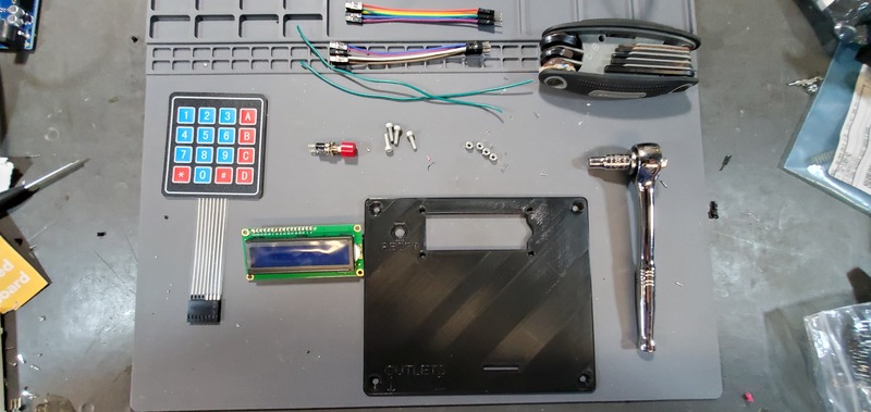
Assemble Faceplate
Parts needed:
- 3D printed faceplate
- LCD module
- 2x 6-pin female-male jumper cables
- 4x4 matrix keypad
- Button
- 2x 20cm solid core 22 AWG wire
- 4x M3 x 0.5 Socket hex head bolts
- 4x M3 nuts
- Metric 2.5 Allen wrench
- 5.5 mm socket wrench
Attaching reset button
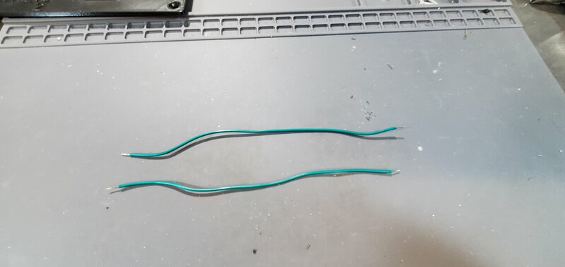
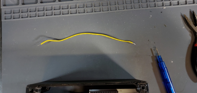
Cut two sections of solid core 14 gauge wire to 20cm. Strip the insulation from ~1cm from each end of each wire.
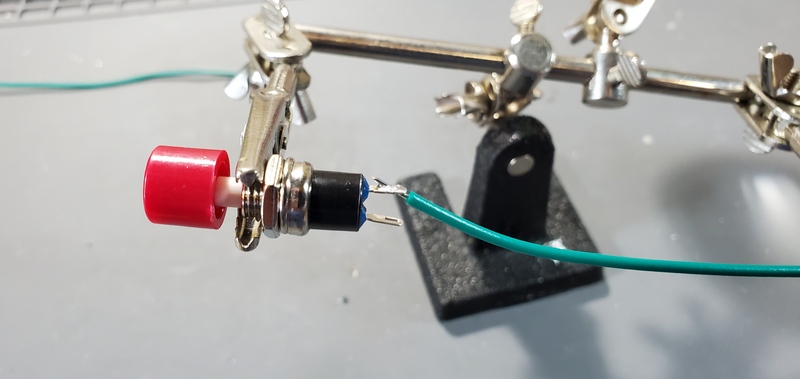
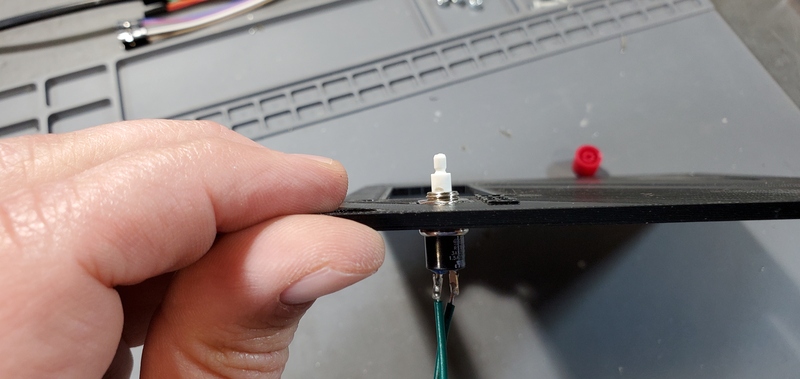
Next, solder one end of each wire to the terminals of the reset button.
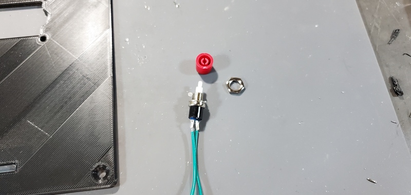
Disassemble the button pulling the red button cap from the button pin. Then, unscrew the nut from the button.
Place the hex nut into the the hexagonal pocket in the faceplate above the “RESET” text.
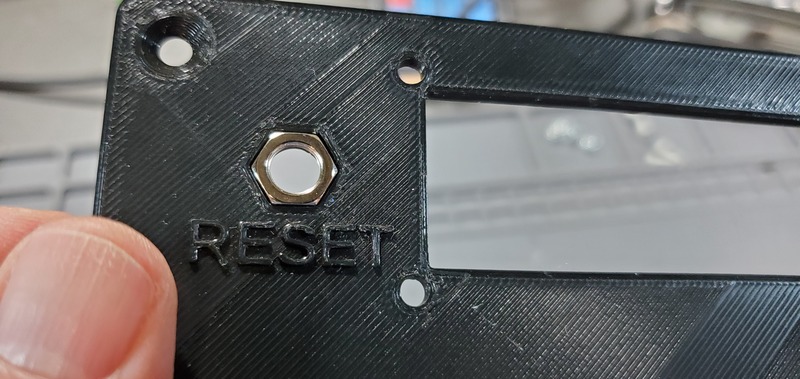
Now, push the reset button through the back face of the faceplate and screw it into the nut until the button assembly is tight against the faceplate.
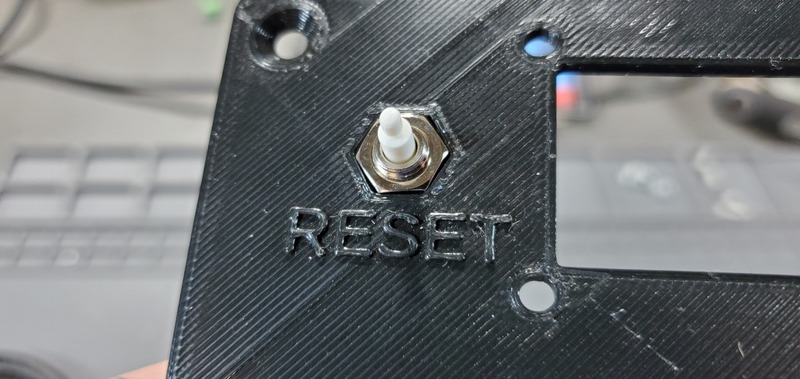
Finally, reseat the red button cap onto the pin.
Attach keypad to faceplate

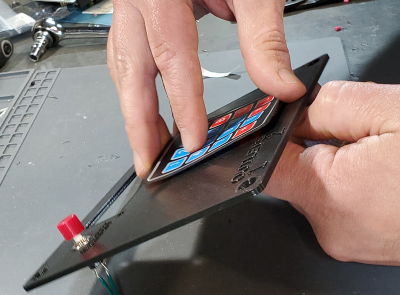
First, peel the paper backing from the keypad.
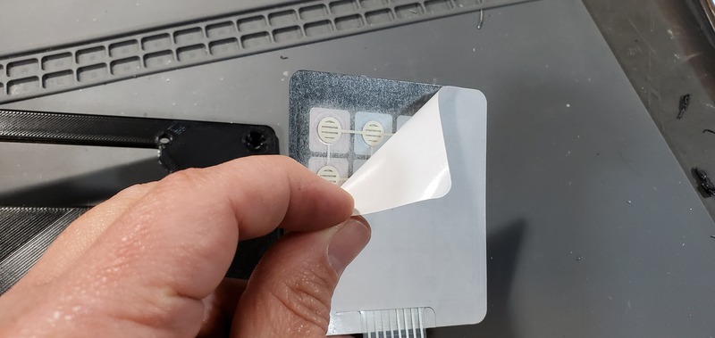
Then, carefully place the female header and flex cable through the slot in the lower portion of the faceplate.
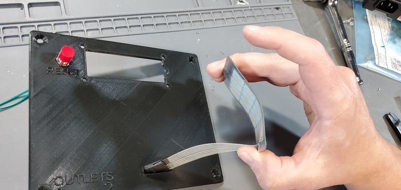
Pull the flex cable through from the back side of the faceplate to take up the slack in the cable with one hand while placing the keypad square (so the bottom edge is parallel with the bottom edge of the faceplate) with the other hand. Once the keypad is placed down on the faceplate, press down firmly on all parts of the keypad to securely adhere the keypad to the faceplate.
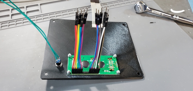
Attach LCD screen to faceplate
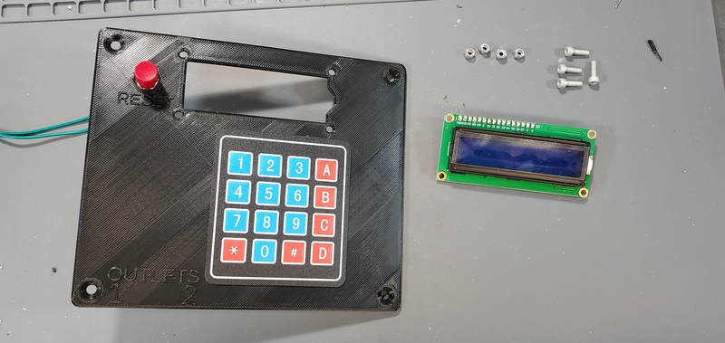
Place the LCD module into the large opening in the top portion of the faceplate from the backside of the faceplate.
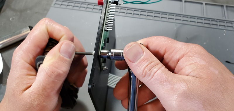
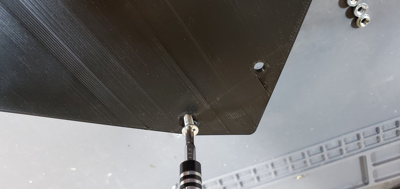
Then, place bolts through each of the four holes through the LCD and faceplate at the corners of the LCD module. Tighten nuts with the Allen wrench and socket wrench.
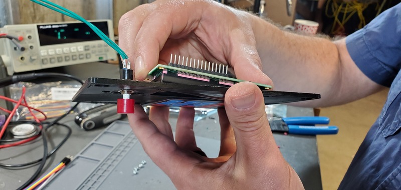
Finally, place female/male jumper cables on the 6 pins on each end of the header pins on the LCD module.
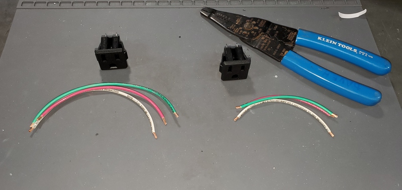
Preparing electrical outlets
Parts & Tools needed:
- 14 gauge stranded wire (three colors: white, green and red)
- one 15 cm section in each color
- one 10 cm section in each color
- 2x panel mount AC outlet
- Strippers
- Soldering Iron
- Helping hands
First, strip 0.5-1 cm of insulation from the end of each section of wire
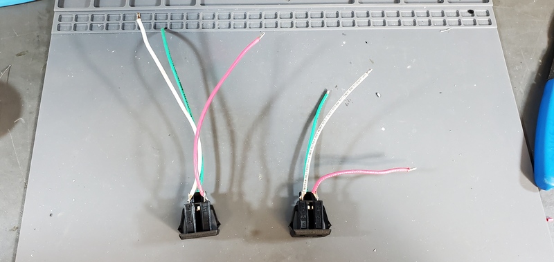
Next, using the helping hands, solder the 15 cm wires to the tabs on one of the AC outlet.
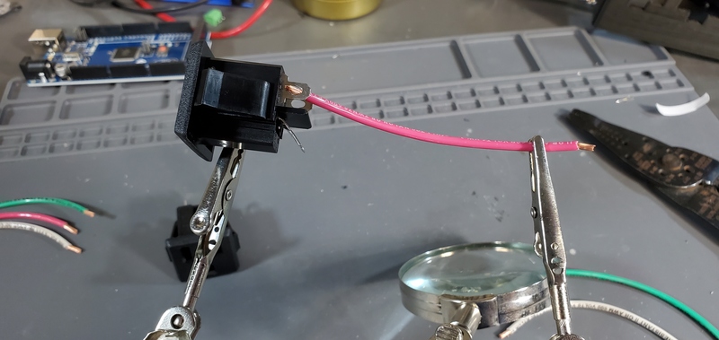
The red wire should be attached to the upper left tab (as you are looking at the tabs straight on), sometimes marked “LM”, the white to the upper left tab, sometimes marked “W”, and the green wire to the lower tab, sometimes also marked “G”. The tin the opposite end with the wires with solder.
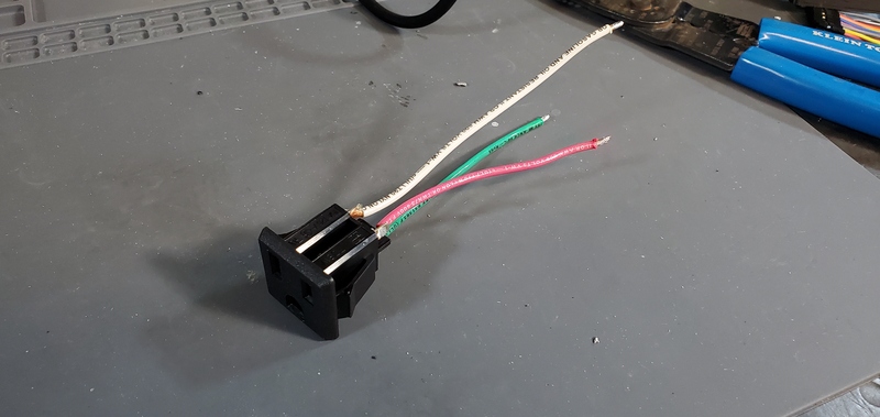
Repeat this process with the 10 cm wires and the other AC outlet. Set these aside for later.
Preparing Housing Skirt
Parts and Tools needed:
- 8x M4 Press-Fit nuts
- At least 1 M4 bolt
- 3D printed housing skirt
- Either 3D printed faceplate or backplate
Place one of the push nuts into the holes in the corners of housing skirt. It will likely not be possible to sink the push nut into the hole by pushing alone.
Because it is generally not possible to push in the nuts with one’s hands, I generally use a bolt to accomplish this. To to this, hold the nut in place with one hand, turn the skirt over and one of the countersunk holes in either the faceplate or the backplate over the hole in which the push nut has been place. Then place a bolt through through that hole and thread it into the push nut.
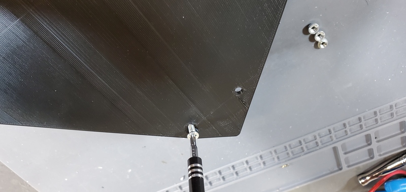
Finally, screw the bolt down to pull the push nut into the hole until the exposed face is flush with the plastic. Repeat in the other seven corner of the skirt.
Final Device Assembly
Parts and Tools needed:
- Prepared housing skirt
- Prepared electrical receptacles
- Arduino Mega 2560
- Arduino Ethernet Shield v1 (WIZnet W5100)
- Assembled PCB
- Assembled faceplate
- backplate
- 2x M3 x 0.5 Socket hex head bolts
- 2x M3 nuts
- Metric 2.5 Allen wrench
- 22 gauge wire >10cm and 0.5 cm stripped at each end
- 8x flat head M4 bolts
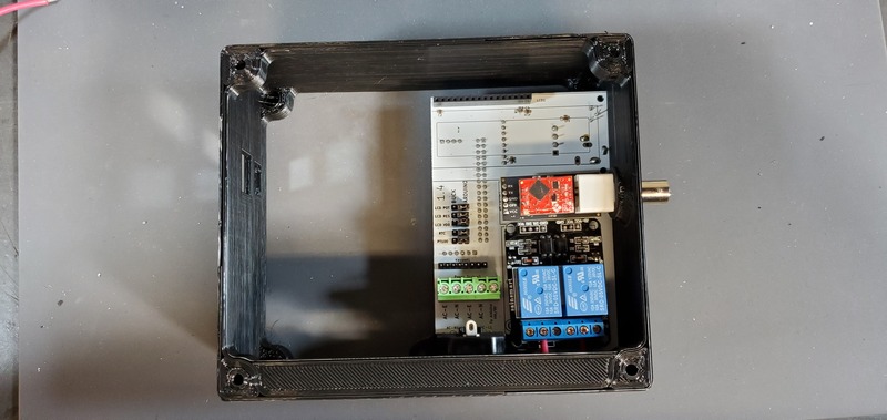
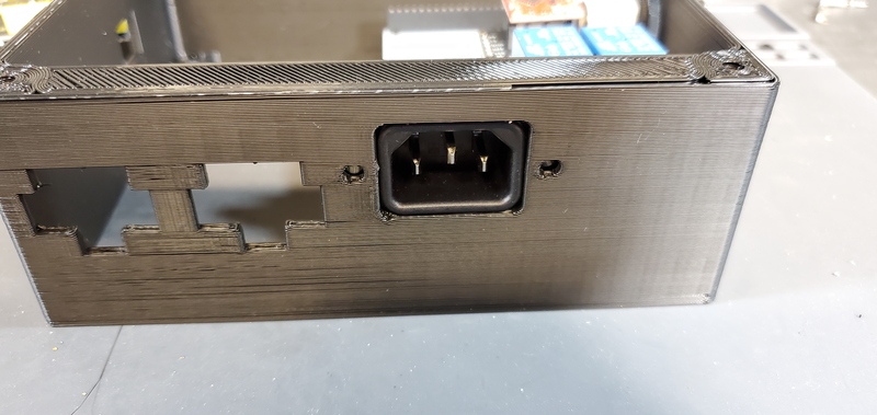
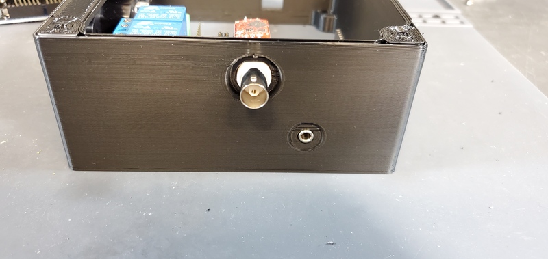
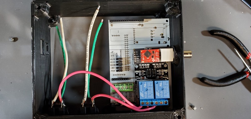
Place the custom PCB into the housing skirt, making sure the three-prong AC power receptacle is positioned into the appropriate hole in the skirt, and that the pH BNC plug and temperature 3.5 mm jack are positioned into their holes as well.
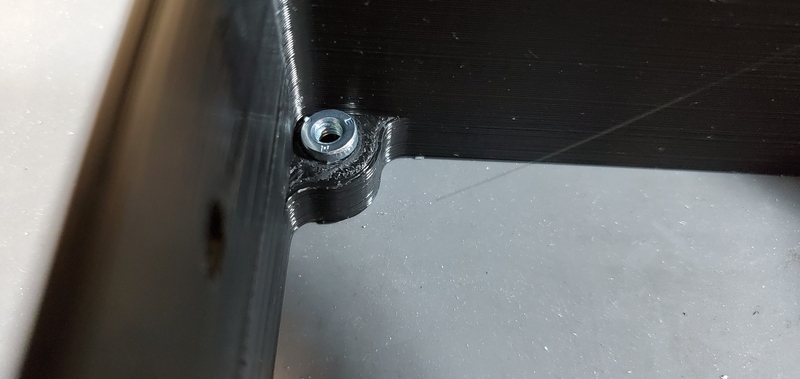
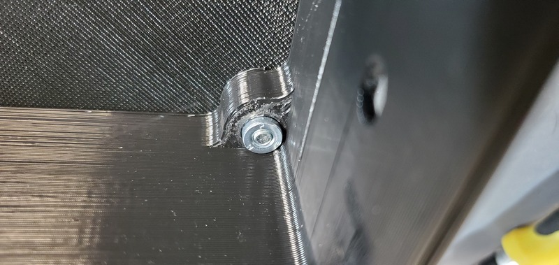
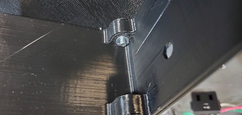
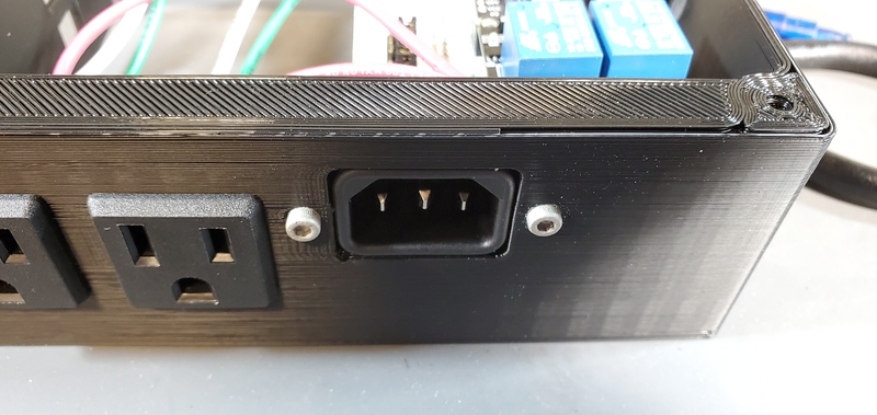
Next, place an M3 x 0.5 Socket hex head bolt through the small holes adjacent to the AC power receptacle. Using pliers (it is difficult to use a socket wrench in this position), place a M3 nut inside the device housing onto end of the bolt. Using a metric 2.5 Allen wrench tighten the bolt onto the nut. The pictures below show these bolts being place after the AC outlets have been places and wired, but the task of placing the bolts is much easier before installing the AC outlets.
Installation of AC outlet live wires
Install the prepared AC outlets into the housing by pushing them, wires first, through the two square openings in the skirt from the outside of the housing. Push them through until they click into place. The AC outlet with the longer (15cm) wires should be placed in the opening farther away from the custom PCB.
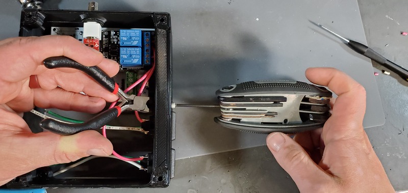
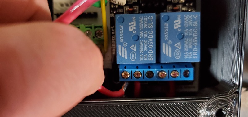
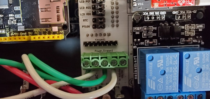
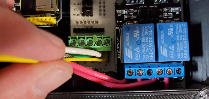
Next, attach the ends of each red wires into the corresponding screw terminals on the 2-relay module. Each relay (the large blue cubes on the module) has three screw terminals. The short red wire to the PCB should already be attached to the center screw terminal of each relay. The red wires from the AC outlets should be attached to the left terminal for each of the relays, with the left AC outlet being attached to the left relay. This works best if the tinned end of the wires are bent in a 90-degree angle to the rest wire before attempting to connect to the relay module. After the wire has been placed into the correct terminal, tighten the screw on the terminal to secure the wire. Pull gently on the wire to make sure it does not easily come out of the terminal.
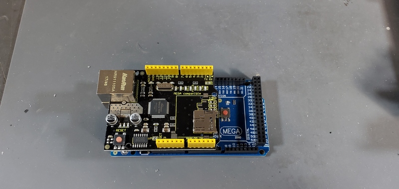
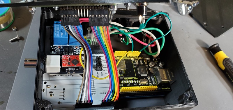
Installation of Arduino Mega and ethernet shield to device
Plug the Ethernet Shield into the Arduino Mega
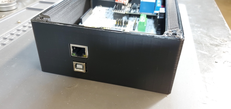
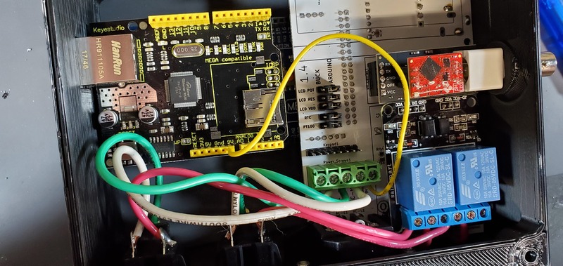
Installation of the Arduino Mega/Ethernet Shield into the housing is most easily accomplished by placing the USB and ethernet outlets on the boards into their respective openings in the housing skirt by placing them at an angle from the backside of the deviReset button wire ce (the side with the buck converters, real time clock and PT100 module on the PCB).
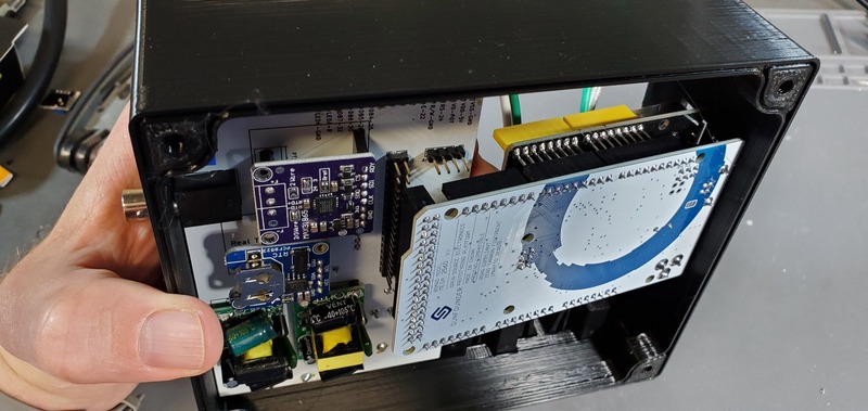
Align the female header pins on the Arduino to align with the male header pins on the PCB, and push them together.
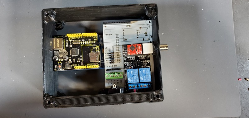
Installation of AC outlet ground and neutral wires and Arduino VIN wire
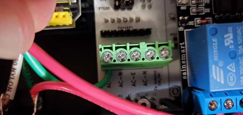
Next, attach the green and white wires of the AC outlet to the large green screw terminal block on the PCB. The green wires should be attached to terminals labeled ‘AC-E’ and the white wires should be attached to the terminals labeled ‘AC-N’. Similar to how the red wires were attached to the 2-relay module screw terminal block, this works best if the tinned ends of the wires are first bent to a 90-degree angle to the wire.
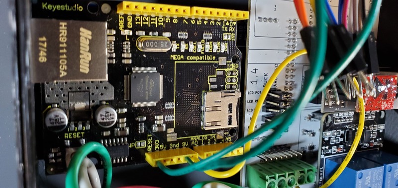
Now you will install the VIN wire for the Arduino to receive power. For this you will use a 22 gauge wire with each end stripped of insulation for about 0.5 cm.
One end of this wire you will connect to the green terminal block position labeled “To Arduino VIN/9V”.
Finally, insert the other end into the Arduino VIN pin on the Ethernet shield. Sometimes this is also labeled “9V”, and is generally between the ground pins, and A0 pin.
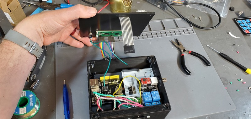
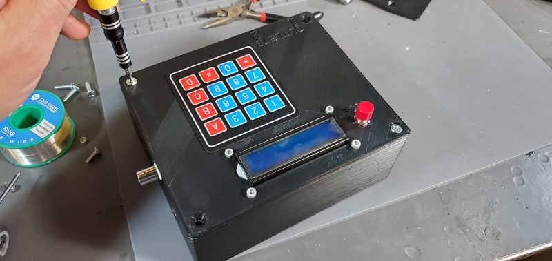
Installing faceplate
Next, install the faceplate to the device
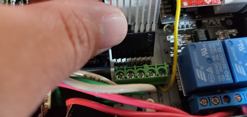
First, attach the keypad cable to the keypad header pins on the PCB.
Second, put one of the wires from the reset button into a ground header on the ethernet shield and the other wire into the reset header on the ethernet shield. Which wire goes into which is not important; they are reversible.
Third, attach the LCD jumper cables to the LCD header on the PCB. Only the outside 6 LCD pins should have attached wires, and these wires should go in the 6 outside-most headers, in the same order they occur on the LCD.
Finally, carefully place the faceplate down on the housing skirt so that no wires are pinched between those two parts and then screw down the faceplate with four M4 flat head bolts.
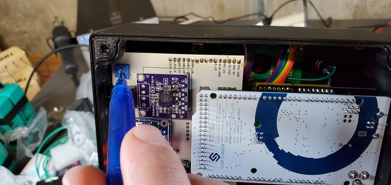
Adjusting LCD contrast
After installing software into the device, but before closing the backplate, you will need to adjust the contrast on the LCD screen before you can likely see anything displayed on it.
Use a standard AC power cable to connect the device to a wall outlet. Then, when the device comes on, CAREFULLY, WITHOUT TOUCHING ANY OTHER INTERNAL PART OF THE DEVICE, use the lcd potentiometer mounted on the back of the PCB to adjust the contrast of the LCD screen.
Attaching backplate
One the contrast of the display is done, you can attach the backplate with 4 M4 bolts.
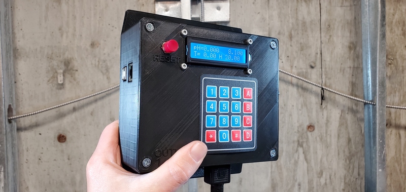
Finished device
Now your device is assembled.